I have decided to try to measure the gravitational field strength at my home as accurately as possible. I have adopted a classic method: the timing of a pendulum's oscillation of known length. I was inspired by the paper The pendulum—Rich physics from a simple system by Robert A. Nelson and M. G. Olsson (Am. J. Phys., Vol. 54, No. 2, February 1986). This paper shows that it is possible, but challenging, to determine an accurate gravity value using a pendulum.
For a small displacement angle θ0 (the maximum angle the pendulum swings away from the vertical), the approximate relationship is:
where T is the amount of time it takes for the pendulum to swing back and forth one time (called the period), L is the length of the pendulum (the distance from the pivot to the weight's center of gravity), and g is the acceleration due to gravity. It is the value of g that I am trying to determine.
For extra precision, the so-called circular error introduced by the actual value of θ0 must be accounted for:
See the Wikipedia article Pendulum (mathematics) for the derivation of these formulas. A conical pendulum has similar behavior, but the math is much easier to understand.
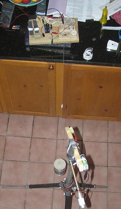
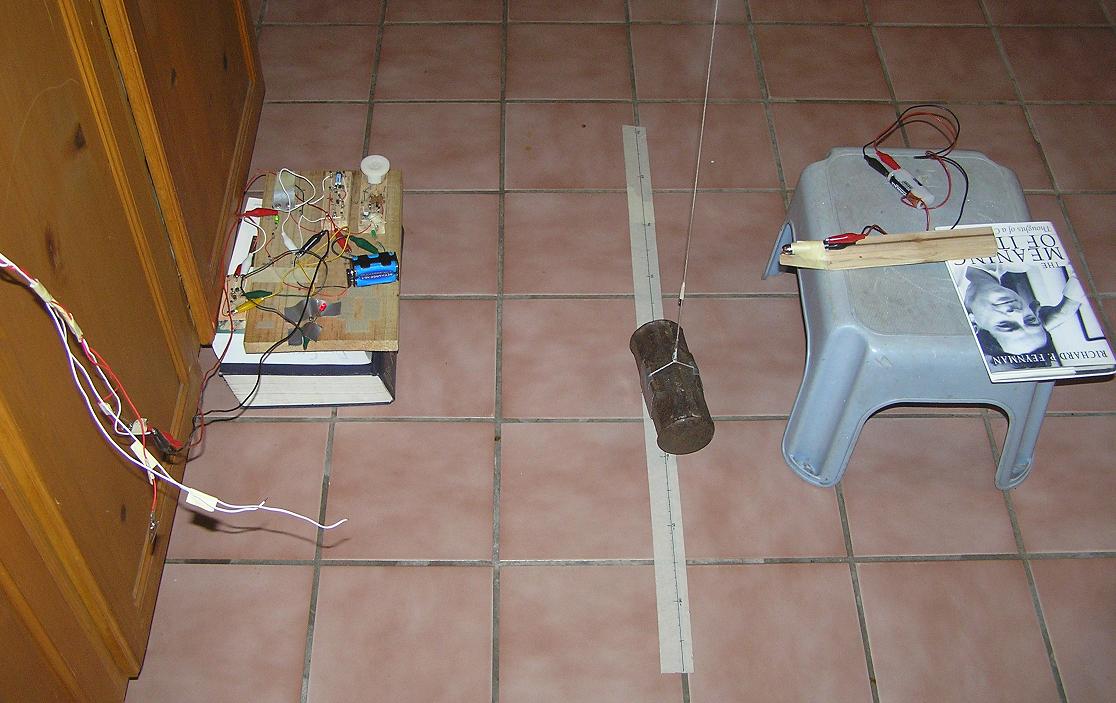
My experimental setup includes a pendulum, a low power laser, a photodetector circuit, and a laptop computer, as depicted below.
|
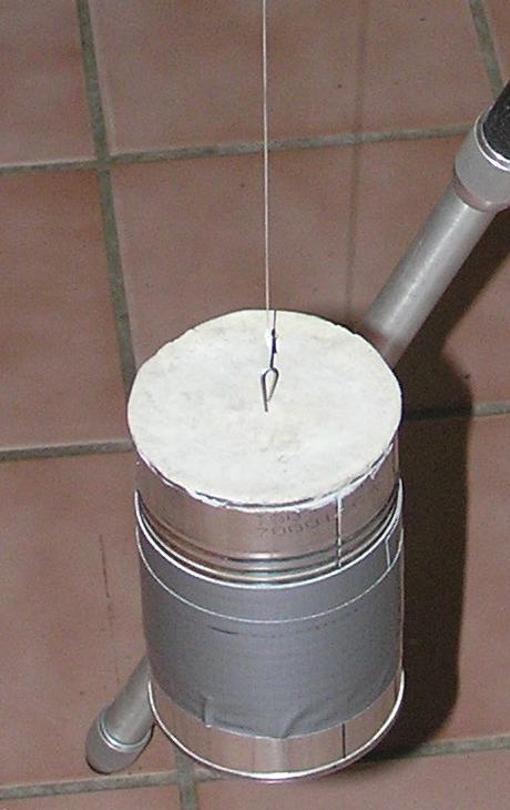
| Sledge hammer head (approx 4.5 kg) suspended from ceiling joist by 2.58 m of nylon twine. As this iron weight swings back and forth, it interrupts the beam from the 5 mW red laser on the right, casting a shadow on the LED to the left (held in place by 2 strips of gray duct tape on the wood board). Each transition from light to dark or dark to light is amplified by a Darlington pair circuit, and then transmitted as a change in logic level on the DSR (Data Set Ready) line of the standard RS-232 serial port inside my laptop (not pictured). |
So far, my repeated experiments are giving answers in the following range, with uncertainty expressed as two standard deviations (95% confidence):
This value for g is fairly close to the value that would be expected for my latitude and elevation in Florida, as determined by the WGS 84 Ellipsoidal Gravity Formula (see Earth's gravity article on Wikipedia) , which is 9.7922 m/s2. The WGS formula models an average sea-level value of gravity across all longitudes for a given latitude, without considerations of local geographically induced distortions to the gravitational field. Once the sea-level value is determined, a simple inverse square law correction is applied using the elevation above sea level.
The Earth's measured gravitational acceleration varies by latitude primarily because of the Earth's spin. Regional variations in mineral composition and geological features such as mountains and continental shelves cause further variations in local gravity. Tidal forces from the Moon and Sun cause fluctuations in local gravity, but they combine on the order of 2×10⁻⁶ m/s2, so they are not measurable by the simple, low-budget experiments I am doing.
In days to come, I will add further entries to this page to explain more in detail how I arrived at my value for local gravitational acceleration, including the mathematics, computer programming, and practical considerations of experimental setup. I also intend to improve my experiment to obtain more accurate values.
Based on the GRACE Gravity Model 02, the gravitational anomaly where I live is very small. The actual measured value should be between 9.792 and 9.793 m/s2. So it definitely looks like my measured value is too small.
I am working on a better pendulum where I can more accurately determine the weight's center of gravity. I want to see if I can obtain about 12 pounds of lead, which would be about right for filling a steel can designed to hold 1 pound of diced tomatoes. A cylinder is a good shape for a pendulum weight because it is easy to measure up the side halfway to find the height of its center of gravity. A small, heavy weight is preferred to reduce the effects of air resistance and moment of inertia.
Last night I stopped at Home Depot and bought a 50-pound bag of concrete mix. Tonight I intend to mix enough with water to fill a steel soup can. (Yes, I have a lot more concrete than I need, but it was the smallest bag they had, and it was only $5.) I am going to do my best to make sure the can is completely filled, with no air gaps, and to insert a reshaped paper clip into the concrete before it sets. I want about half of the paper clip wire to stick out of the top of the can as close to the center as possible. I believe I will need to bend the bottom of the immersed part of the paper clip at a right angle so that it can't possibly slip out of the concrete once it hardens.
Once the concrete is cured, I will carefully bend the protruding bit of the paper clip into a hook shape and try to balance it as best I can. The goal is to be able to suspend the weight directly above its center of gravity, so that the can hangs level. When I am done, the total weight should be about 2.3 pounds, and the mass should be just over 1 kg.
Although the center of gravity should be about halfway up the height of the can, there are some imperfections in this estimate. For one thing, the steel can itself has a different density than the concrete that will be inside it. The can has a steel bottom, but no balancing steel top. The shape of the can is not a perfect cylinder, having grooves on the side and a recessed bottom that isn't flat.
Finding the exact height of the center of gravity is crucial to improving the accuracy of my gravity measurements. I want to figure out a way to find the balancing point of the finished can when it is turned on its side. One idea is to put the can on its side on a flat desk and slowly push it over the edge to see where it starts to tip. Another idea is to fashion some kind of circular band with hook on it that fits the outside of the can, and move it back and forth to see where it levels out. I have no doubt that I will need to try a variety of approaches to find something that works. However I find the height of the center of gravity, I will need to mark it as a line that runs all the way around the can so that I can measure to it before each experiment.
I now have concrete in a can! Here is what it looks like:
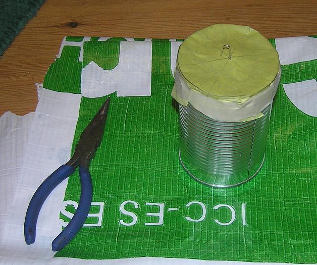
I made a paper guide for the top to allow me to determine the center position where the paper clip wire should go. That wire will be the hook that I tie the string to. The paper guide also serves to hold the paper clip in place while the concrete is curing overnight. I made it by tracing the can's top onto a sheet of paper. I used compass and straightedge to find the center of the circle by constructing three diameters of the circle. Even though two diameters would be enough, making three is more of a sanity check.
One problem I ran into is that I didn't understand what I was buying when I bought this concrete. It was chock full of gravel, which would make it hard to keep an even density throughout the can, and even worse, it would be pretty hard to get the paper clip wire inserted properly. So I had to take a colander and sift the concrete mix to get pure cement powder. I don't have much experience with mixing concrete, but I added just enough water that it was thouroughly wet, without being soupy. I put on some rubber gloves and hand-packed that concrete into the can as carefully as I could, trying to avoid any air gaps inside.
Now, all I can do is wait 24 hours to see how it looks. The concrete might stick to the paper, but I don't think that will be a big deal; if so, I will just cut off all the paper around the side as neatly as I can.
I continued experimenting with different pendulum weights and string materials this weekend.
I mounted the concrete can (what I call Pendulum #3) for the first time on Saturday. I determined the distance from the center of gravity to the pivot point to be L = 2.693 m. I ran three timing trials with this length L, but I got an unacceptably large standard deviation for the first run (σ = 2.2 ms). I kept data from the second and third run, both of which had σ of about 0.5 ms.
|
|
Next I tried raising the pendulum weight, which reduced L to 1.634 m. I have reason to believe that the string stretched the weight lower after the first run, giving me too low a value for gc, so I kept only the first run. (From now on I need to make sure to measure L before and after each run!)
I started wondering if there was something about the thick nylon twine that caused some kind of distortion to the experimental results. Perhaps the twine was not bending exactly at what I thought was the pivot point. So I tried replacing the nylon twine with some dental floss, which is much thinner, and perhaps more flexible.
Finally, I doubted the accuracy of my determination of the concrete can's center of gravity. I decided to find an object in my junk collection whose center of gravity could be determined by geometric symmetry. I stumbled upon a small rectanguloid brick of alumninum. It measures 6.60cm × 3.15cm × 2.19cm. It has rounded corners around the longest of the 3 axes, each having an approximate radius of curvature of 0.2cm. I suspended the aluminum brick (Pendulum #4) with the longest axis oriented vertically and ran three timing trials, only one of which ended up having a small enough timing uncertainty to be kept.
Here is a summary of all my data and calculations that I judge to be valid from this weekend. Note that timing uncertainties are all given as ±2σ, and gravitational uncertainties are based on calculating gc = L (2π /
| L [m] | t [s] | tc [s] | gc [m/s2] | Notes |
|---|---|---|---|---|
| 2.693 | 3.29743 ± 0.00095 | 3.297290 | 9.7787 ± 0.0056 | #3 Concrete Can with nylon twine |
| 2.693 | 3.29718 ± 0.00115 | 3.297106 | 9.7798 ± 0.0068 | #3 Concrete Can with nylon twine |
| 1.634 | 2.57025 ± 0.00123 | 2.569085 | 9.7736 ± 0.0094 | #3 Concrete Can with nylon twine |
| 2.330 | 3.06814 ± 0.00173 | 3.067905 | 9.7731 ± 0.0110 | #3 Concrete Can with dental floss |
| 2.4715 | 3.15751 ± 0.00124 | 3.157459 | 9.7869 ± 0.0077 | #4 Aluminum Brick with dental floss |
My conclusion so far is that the concrete can must have a lower center of gravity than I determined. My means of finding the center of gravity was to see what the tipping point was when it was placed on its side and slowly pushed off the edge of a table with a flat edge. One of the problems with this method that I did not anticipate was that the edge of the can is grooved, so it is not possible for every point on its edge to act as a fulcrum.
My goal for next weekend is to proceed with finding a more compact and dense pendulum weight with uniform density and a geometrically regular shape (cylinder or sphere). I also want to investigate techniques for supporting the pivot point other than hanging the string over the bottom part of a screw eye.
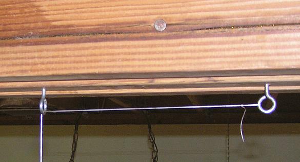 |
| I have used a pair of screw eyes as a pivot for my pendulum experiments so far. I make a knotted loop at the end of the string and attach it to the hook on the right. Then I feed the string through the hook on the left. This means that the effective pendulum length changes very slightly as the pendulum swings back and forth, but I am assuming the change is negligible for the small displacement angles I am using (typically less than 4° of arc). I measure L from the midpoint of the bottom of the left hook to the weight's center of mass. The distance from this midpoint to the floor is 284.0 cm. |
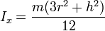
One of the assumptions I have been making all along is that I can ignore the moment of inertia of my pendulum weights. However, when I go back and include this in my calculations, it causes my estimate of g to go up by a factor of 1.0002 when L = 2.693m, or by 1.0005 when L = 1.634m. This is based on the formula for Ix for a solid cylinder as seen in this list of moments of inertia.
I assume a uniform density for the concrete can, even though the thin shell of steel is denser than the concrete inside. The can has height h = 0.112m and radius r = 0.037m. Here is my mathematical derivation for the moment of inertia corrections:
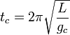
The formula I have been using for relating the angle-corrected gravitational acceleration gc to the angle-corrected period tc, based on the idealization of a point mass, is:
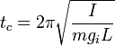
When using a pendulum based on a distributed mass with total moment of inertia I, the moment-corrected gravitational acceleration gc is related by:
Equating these two values for tc, canceling like terms, and squaring both sides, we have:
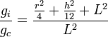
Solving for the ratio of moment-corrected gravitation over angle-corrected gravitation:
The moment of inertia of a solid cylinder rotating about a line through its diameter, passing through its center of mass is:
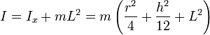
Using the Parallel Axis Theorem, we can calculate the total moment of inertia as the cylinder pivots about a point that is a distance L above its center of mass:
Substituting this value of I into the gravitation ratio equation, we have:
This ratio determines the amount we need to multiply in order to correct for moment of inertia in each gravitational measurement based on a cylinder hanging by the center of one of its circular faces.
Here is an updated table with moment-corrected gravitational accelerations. In the case of the aluminum brick pendulum weight, I corrected for the moment of inertia of a right rectangular prism, averaging for the two extreme values possible depending on the orientation of twisting around the support string. These two moment of inertia values, divided by the unknown mass (which cancels out of the equations anyway) were 7.30×10⁻⁵ m2 and 6.60×10⁻⁵ m2. These values differ by only 11%, so the average value of 6.95×10⁻⁵ m2 seemed reasonable.
| L [m] | t [s] | tc [s] | gi [m/s2] | Notes |
|---|---|---|---|---|
| 2.693 | 3.29743 ± 0.00095 | 3.297290 | 9.7806 ± 0.0056 | #3 Concrete Can with nylon twine |
| 2.693 | 3.29718 ± 0.00115 | 3.297106 | 9.7817 ± 0.0068 | #3 Concrete Can with nylon twine |
| 1.634 | 2.57025 ± 0.00123 | 2.569085 | 9.7787 ± 0.0094 | #3 Concrete Can with nylon twine |
| 2.4715 | 3.15751 ± 0.00124 | 3.157459 | 9.7876 ± 0.0077 | #4 Aluminum Brick with dental floss |
This is heading in the right direction for what I expect to measure, namely 9.792 m/s2. This emphasizes the importance of using a smaller object as a pendulum weight, and using one that is a simple geometric shape whose moment of inertia can be calculated easily, and finally that the shape should be radially symmetric about the axis of suspension, so that the moment of inertia remains constant when the string inevitably twists a little bit during experiments.
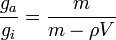
In reading over the Nelson and Olsson paper again, I realize that a couple of corrective factors I want to tackle next are the buoyancy of air and the mass of the string. The buoyancy of air matters because it reduces the weight force of the pendulum, while not affecting its inertial mass. I thus need to multiply my gravity estimate by
where ga denotes the gravitational acceleration corrected for air buoyancy, ρ is the density of air, and V is the volume of the pendulum weight.
So tomorrow I am going to bring in my weights and strings to work and use a friend's scale to determine the relevant masses. I already know the dimensions of the concrete can, aluminum brick, and steel sphere ball bearing sufficiently to calculate their respective volumes.
I have done my best to correct for the buoyancy of air. I am assuming that all of my experiments were done at a temperature of about 25°C with a barometric pressure of about 101.3 kPa. This yields a dry air density of 1.184×10⁻³ g/cm3. I am ignoring humidity because I don't think it would make much difference, but for the record the relative humidity in my house this time of year tends to be about 60%.
Here are my air buoyancy corrected gravity measurements (ga), calculated by multiplying the air buoyancy correction factor for each pendulum weight by ga, which is the previously determined value corrected for moment of inertia (see above).
| Pendulum | #2: Ball Bearing | #3: Concrete Can | #4: Aluminum Brick |
| Mass [g] | 286 | 1100 | 125 |
| Volume [cm3] | 37.2 | 454 | 45.3 |
| Density [g/cm3] | 7.70 | 2.42 | 2.76 |
| gi [m/s2] | 9.7876 | 9.7803 | 9.7876 |
| Correction factor | 1.000154 | 1.000489 | 1.000429 |
| ga [m/s2] | 9.7891 | 9.7851 | 9.7918 |
I did some more correction for the moment of inertia, this time for the nylon twine I used in the concrete can pendulum. That increased the gravitation estimate from 9.7811 m/s2 to 9.7901 m/s2. This means I am very close to the NASA value of 9.7922 m/s2 for my geographic location! I found it interesting that the twine's moment of inertia was about 6 times that of the concrete can, even though the twine has a much smaller mass. It is because the twine extends over a much longer distance, and moment of inertia units have a squared distance factor.
Today I left work a little early to go to Skycraft to look for junk I can use in my pendulum experiments. I was hoping to find some cylindrical or spherical hunks of solid metal, but I only ended up buying a couple of aluminum rods. One is a solid rod, and the other is a hollow tube. I don't have any good way of weighing them yet, but here are the dimensions:
| Rod | Tube | |
|---|---|---|
| Length [cm] | 122.2 | 132.1 |
| Outer diameter [cm] | 1.9 | 2.5 |
| Inner diameter [cm] | — | 2.05 |
The idea is to try making a solid single-piece pendulum out of these, now that I understand how to calculate gravitation from the behavior of regular geometric solids using their moment of inertia. For example, maybe if I drill a hole through one end of the solid rod and fit a pivot pin through the hole, I can make the rod swing back and forth, time it, and get a more accurate gravity estimate with far fewer terms to correct. Even better would be if I could do this in a perfect vacuum with the rod suspended by a frictionless magnetic bearing, but currently that's far beyond my technical means and budget.
This morning I stopped by the post office on the way to work. They were kind enough to weigh my newly-acquired aluminum objects for me, though their scale reads only pounds and ounces. I hope I can get more accurate values later. Here is the updated table, which also contains calculated volume and density values. The densities are in line with what I would expect for an aluminum alloy. (Pure aluminum has a density of 2.70 g/cm3.)
| Rod | Tube | |
|---|---|---|
| Length [cm] | 122.2 | 132.1 |
| Outer diameter [cm] | 1.9 | 2.5 |
| Inner diameter [cm] | — | 2.05 |
| Volume [cm3] | 346.5 | 212.4 |
| Mass [kg] | 0.96 | 0.57 |
| Density [g/cm3] | 2.78 | 2.67 |
Visits to this page since 14 April 2009:
![]()