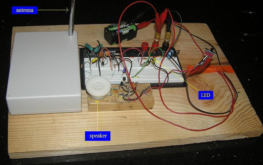
I am building a lightning detector based on a clever design by Charles Wenzel. It is basically an AM radio receiver that is tuned below the AM broadcast band, to around 300 kHz. Mine will employ one of Mr Wenzel's options: it will flash a green LED with every lightning strike. However, I am changing the design to optionally beep a 1 kHz tone for each strike, instead of the crackling audio option that he presents on his web site. I will have a switch to turn just the beeper on or off without affecting the rest of the circuit.
So far I have a prototype that seems to be working. I say "seems" because there haven't been any thunderstorms nearby, but it does go off whenever I turn certain electrical devices on or off. It really responds to the ceiling fan!
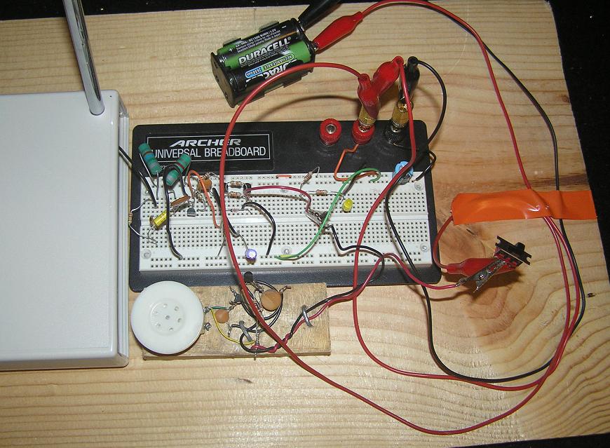
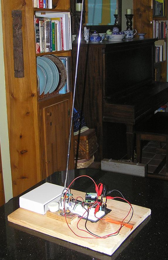
Below are some photos of the prototype. Once I have a real storm to test it with, and I can confirm it is working as expected, I will begin the process of soldering the circuit down to a perf board and mounting it inside the plastic enclosure that you see on the left of each photo. I already have the telescoping antenna mounted.
As I arrived home from work today, there was a thunderstorm approaching. I went indoors full of excitement and powered up the lightning detector prototype. And...
IT WORKS!It flashed and beeped in synchrony with every bolt of lightning! So now that I have confirmed that the design and the parts I used to implement it are all working, I will soon begin the process of planning the perf board layout.
Actually, first I need to install fresh parts for the beeper onto the breadboard and test them out. I have a rule of never soldering any part down unless I have seen it working first in a prototype circuit, and the beeper I am now using is a separate module that I don't intend to include in this project's final form.
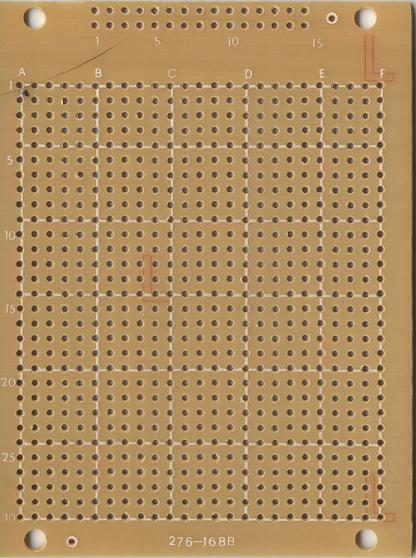
At any rate, here are photos (flatbed scans, actually) of the front and back of the perf board I will use. I need to plan out the placement of all the parts in exact detail before I begin final assembly. I find it is hard enough to concentrate on installing parts and soldering them, without having to make layout decisions at the same time.
 |
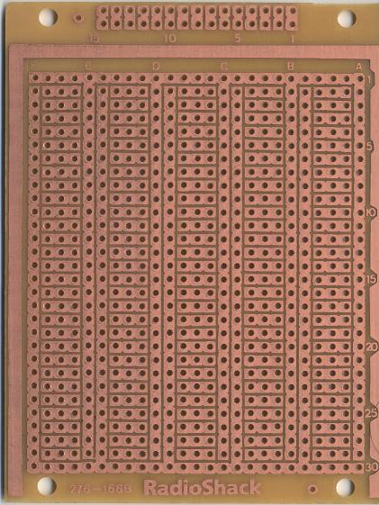 |
| perf board front | perf board back |
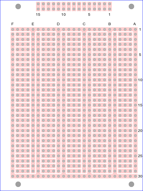
To help me plan out the exact layout of the circuit before I start soldering, I have created an image of the perf board that I can print out and draw on. Instead of using some drawing program to tediously draw this, I thought it would be more fun to write a program to generate the image for me.
I just started learning the Python programming language, and I really like it. Python made this task very easy, because there is a free graphics file package available for it called the Python Imaging Library (PIL).
Here is the source for the program I wrote (note that you will have to rename the file to have a .py extension if you download it):
MakePerfTemplate.py
And here is the PNG file it generates. Note that this is the back side of the perf board, showing where all the copper foil traces are. You can use Microsoft Paint (or whatever) to open this image, flip it horizontally, and print it out, to get an effectively transparent image of the front side, if you prefer to plan part placement from the side the parts actually rest on.
I had a very busy weekend planning and building the finished lightning detector.
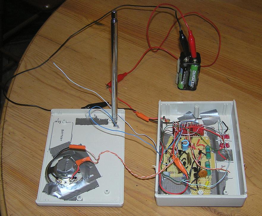
|
| The finished circuit on the perf board, mounted inside the plastic enclosure. Yes, I love duct tape! The antenna and the 50Ω speaker are mounted to the inside bottom of the enclosure. There are some holes drilled through the bottom, directly beneath the speaker, for the sound to come out. The outside bottom of the enclosure has little rubber feet that leave an air gap beneath the box, which is plenty for a nice loud beep to be heard even when the box is closed tight. The main circuit board hangs from the inside top of the enclosure. |
|
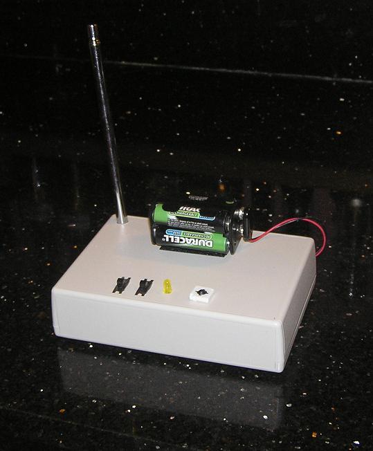
Here is what the lightning detector looks like now with everything tucked safely inside the enclosure.
It turns out I did not have room inside for the battery pack after all, so I mounted it on top
using velcro. This is fine with me because I would rather not have to open the box up to
recharge the batteries anyway. The components on the top front, from left to right, are:
|
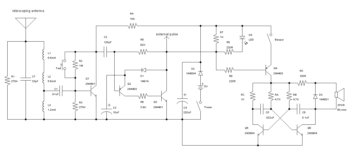
Here is the schematic of the finished lightning detector:
Below is a link to the original schematic file in TinyCAD format.
(To download this file you may need to right-click and choose "Save As...".)
lightning_detector.dsn
Last night we got some nearby lightning activity, and the lightning detector worked quite well. This is the first real-world test after sealing up the enclosure. I'm about to take it home from work, and a storm is approaching, so I might get to find out if it works inside the car!
I'm working on a new, generic Python program for generating board images based on XML input files: