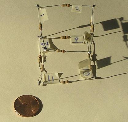
Figure 1.
There are much worse resistor problems than this, but this one has a solution!
There are 3 cases of distinct resistance measurements that one can make on a cubical resistor network with all 12 resistors the same:
First, let us use the label on each of the cube's 8 corners to represent that corner's voltage level. We will arbitrarily apply 1 volt of potential across corners A and G, so we define A = +1 volt and G = 0 volts (ground).
Using symmetry, we can determine that certain corners must have the same voltage, and certain resistors must be carrying identical amounts of current. Specifically, the voltages B, D, and E must all be the same: B = D = E. Imagine rotating the cube around an axis along the line connecting corners A and G, and you will see that B, D, and E are interchangeable. By similar analysis, the three corners H, F, and C must have the same voltage: H = F = C.
The current flowing through resistors R1, R2, and R5 must be the same value. Let us refer to this amount of current as i=(A−B)/R. As stated above, we are applying a voltage of 1 volt across the corners A and G, so can imagine a 1-volt battery with the positive terminal hooked up to A, and the negative terminal hooked up to G. The current flowing into A from the positive terminal of the battery, and the current flowing out of G into the negative terminal of the battery must both be 3i. The 3i of current leaving G and going back into the battery must be equal to the total current entering G via resistors R7, R10, and R11. By symmetry again, these currents must each be the same value i.
Let us simplify and redraw the diagram using these symmetry constraints:
Now we need to figure out the currents flowing through the resistors that connect B-volt corners with C-volt corners. These currents must all be identical, simply because they are all equal to (B−C)/R. Since the current flowing into a B-volt corner is i=(1−B)/R, and there are two symmetrically equivalent branches where the current must exit, those currents must be i/2 = (B−C)/R. Let us add these currents to the diagram:
So now we know that i = (1−B)/R = (C−0)/R = 2(B−C)/R. Simplifying and multiplying through by R, we have:
We can substitute 1−B for C and obtain:
Now we have everything we need to calculate the equivalent resistance Q as measured across distant corners A and G. We can calculate that the current i = C/R = (0.4 volts)/R. The equivalent resistance Q is determined by noting that the total current flowing through the cubical network is 3i, and the total voltage drop is 1 volt:
So for a cubical network of identical resistors R, the resistance measured across opposite cube corners is (5/6) R.
| R1 = 98.8 | R7 = 99.4 |
| R2 = 99.2 | R8 = 99.6 |
| R3 = 99.1 | R9 = 99.0 |
| R4 = 99.4 | R10 = 99.6 |
| R5 = 98.9 | R11 = 99.9 |
| R6 = 99.6 | R12 = 99.7 |
After recording these measurements, I soldered together the resistors in the cubical configuration, being careful to arrange them so that the labels R1 through R12 exactly matched the layout shown in Figure 1.
Based on my mathematical analysis, using the average resistance value (R1+R2+...+R12)/12 = 99.35 KΩ, the predicted equivalent resistance Q should be (5/6)(99.35 KΩ) = 82.79 KΩ. When I actually measured across corners A and G, I obtained the value 82.8 KΩ, which is identical within the limits of my multimeter!
Here is a complete table of measurements across every possible pair of corners, again with all measurements expressed in KΩ. Note that redundant entries beneath the diagonal of zeroes have been omitted for the sake of clarity. I have also color-coded the 3 broad cases of corner relationships:
green = adjacent,
cyan = diagonal on same face,
brown = opposite corners.
| A | B | C | D | E | F | G | H | |
| A | 0 | 57.9 | 74.4 | 57.8 | 57.8 | 74.6 | 82.8 | 74.6 |
| B | 0 | 58.0 | 74.6 | 74.6 | 58.1 | 74.7 | 83.0 | |
| C | 0 | 58.1 | 82.9 | 74.6 | 58.1 | 74.7 | ||
| D | 0 | 74.6 | 82.9 | 74.7 | 58.2 | |||
| E | 0 | 58.8 | 74.7 | 58.1 | ||||
| F | 0 | 58.1 | 74.7 | |||||
| G | 0 | 58.2 | ||||||
| H | 0 |